
Top Board.
Thanks to: me (PoTom)
Virtual
TvMaN
AzRael
][eBerg
[DoPeMaN]
BanpaiA team and everyone in #cellular
Requrements: wire, soldering iron, screwdriver, pliers,
1/8" or 3/32" mono Audio jack,
20-30k ceramic Filter (SFG 455 B6 F; KBF-455R-20(30)A, etc)
0.1uF capacitor (not required).
1. Dissasemble scanner :
remove battery, antenna, knobs;
unscrew 4 screws on the bottom;
gently pry lower part of chassis;
unscrew 4 hex screws on top board;
unsolder 2 (volume and squelch) leads and 2 antenna leads;
disconnect 2 wires (squelch and volume) from sockets;
pull top board up.
2. Replace IF Filter to 20-30K one [#4],
you may use Filter from Motorola
Brick or Bag phone (ex: SFG 455 B6 F)
or KBF-455R-20A (KBF-455R-30A)
order from www.marshall.com.
Find 3 filter solder leads
[#7] on bottom side of the top board and carefully unsolder them
pulling filter up, put new
filter in that place and heat those 3 solder points pressing filter in.
3. Baseband audio(from discriminator) output.
Find discriminator chip
[#2] on top board;
Solder one lead of
0.1uF capacitor [#3] to pin 9 [# 1] of discriminator chip [#2];
Solder wire [#5] to second
lead of capacitor [#3] .
(you may not
install capacitor at all, everything will still work without it).
4. 800-900Mhz restoration . (apllies to scanners produced
before April 1994)
If your scanner still has
800-900mhz zaps, to restore it go to lower board
(unscrew 3 screws on middle
board, disconnect power wire from lower board, pull board up),
cut diode D-11 (Pro 34)
or D-13 (Pro 37) [#8].
5. Audio jack installation.
Since I didnot find any
good place for jack, I removed CHARGE jack [#9] from power board
and installed audio one
[#6] in that place.
Connection is simple ,
tip goes to wire [#5] , shield goes to GROUND (any place is good).
Assemble scanner and enjoy.
Top Board.
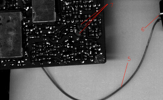
Bottom of Top Board.
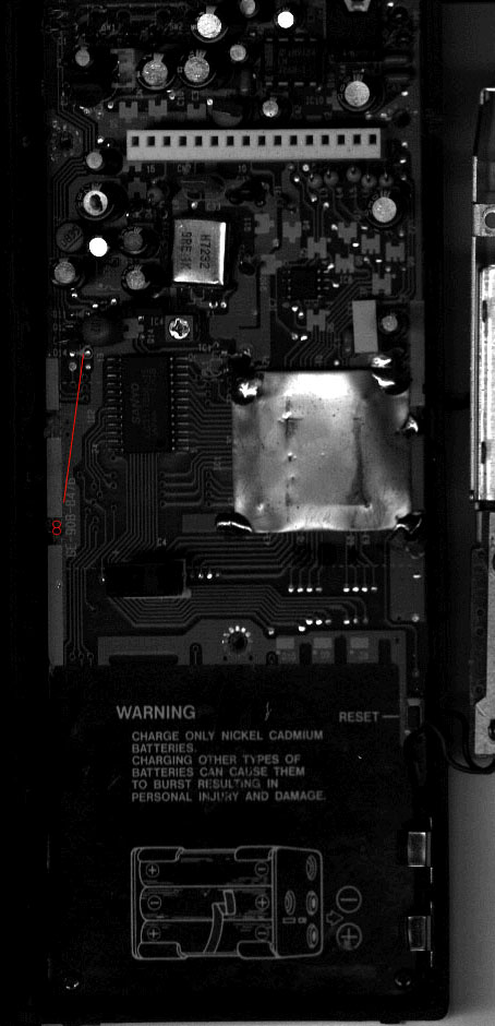
Lower Board.
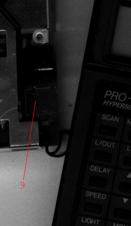
Part of Midlle Board (Power board).